Guest Article by Ethan Yakhin from Acuity Training on how to draw a Connecting Rod and Piston in AutoCAD.
NOTE: Measurements in tutorial not actual size of a Connecting Rod or Piston. However, the sizes are proportional.

This tutorial relies heavily on correct grid click and proper snap settings. Before beginning the tutorial, make sure your grid and snap setting look like this:
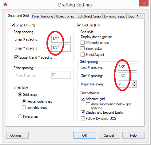
(Figure 1)
Your Object Snap settings should look like this:

(Figure 2)
Once your snap settings match mine, we will be ready to begin. We will be making a 2D representation of both a Piston, and a Connecting Rod. A Piston is a critical part of every car engine, and is a key part of the intake process. A Connecting Rod is a part that connects a Piston to a ‘crank’ or ‘crankshaft’.
PART 1: Connecting Rod (without) Piston
First, start by making a circle (C) with a radius of 3.5 inches. Make sure this circle is centered on a major grid point.
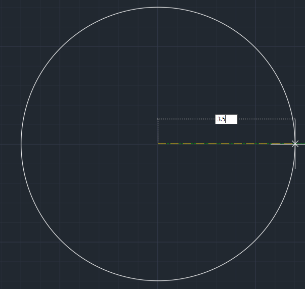
(Figure 3)
Next, you want to make a copy (CP) of our circle and place it in the same location as in Figure 4. Do not leave the CP command yet. With the snap settings we have set, it should be no trouble at all.
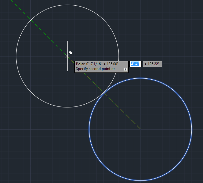
(Figure 4)
Add another copy at the location show in Figure 5. After clicking, you can leave the CP command.
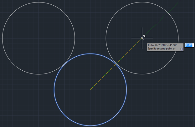
(Figure 5)
Next, go back to the centre of the original circle, and make another one that has a radius of 3 inches.

(Figure 6)
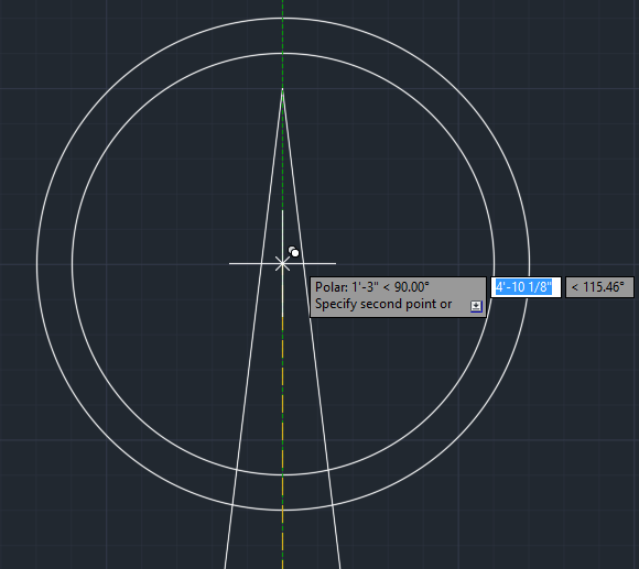
It is going to get tricky now so make sure you follow the direction closely. Make a Line (L) with a start point on our first circle’s North Quadrant, and an end point 1’2” above that. Wait for further instruction before escaping the Line command.

Figure 7
With the Line tool still active, place your next click on the West Quadrant of the third circle we made.
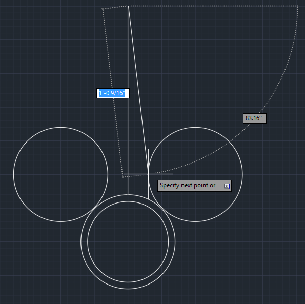
Figure 8
Place your next click exactly 3” West. Then, finally, place your final click on the top of the first line we created. After this you can leave the Line Command.
(Figure 9)
You can delete the horizontal line. We won’t be needing it.
Refer carefully to Figure 10 for the next part. Using the Line tool (L), follow the clicks sequentially using the 4 endpoints circled in Figure 10.
(Figure 10)
Using the Trim tool (TRIM), select the 4 lines highlighted in Figure 11, and then press ENTER
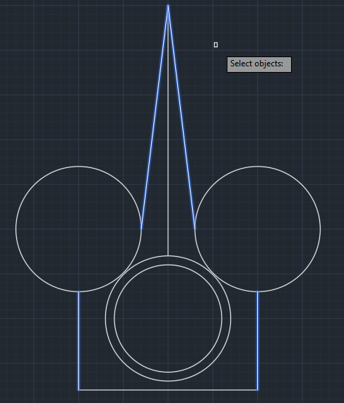
(Figure 11)
After hitting ENTER, Select the outer parts of the left and right circle. Those part should, disappear leaving only an arc. Hit ENTER again to leave the Trim Command.
(Figure 12)
Delete the Vertical Line. We will not need it anymore.
Make a copy (CP) of our 2 center squares, and place it as show in Figure 13.
(Figure 13)
Scale (SCALE) the copy down to half of the original’s size. Make sure the centre point remains the same. After scaling it down, open up the Trim command againd. Select the outer circle and trim out every straight line that is within or above the 2 circles. You should end up with Figure 14.

(Figure 14)
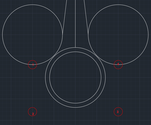
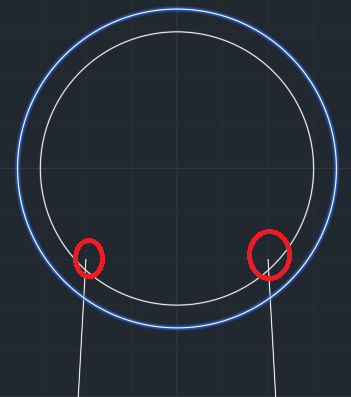
Using the Line command, click the grid points circled in red in Figure 15, moving in numerical order. You may have to zoom in on Figure 15 to properly see all the numbers.
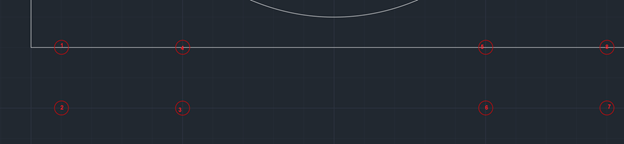
(Figure 15)
Often when designing things that involve arcs and straight lines missing, things end up a little deformed. To resolve this all that is need is proper adjustment. Move the endpoints of the 2 highlight lines from points 1 to points 2 (Figure 16), and trim the excess tips that are circled in Figure 17
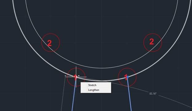
(Figure 16)
(Figure 17)
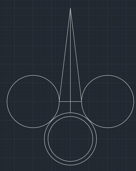
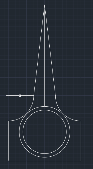
Our Connection Rod is much better and now looks complete!
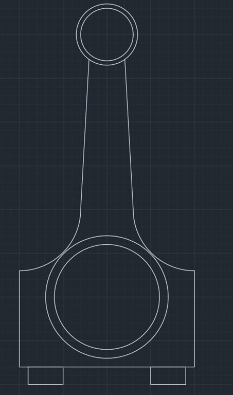
(Figure 18)
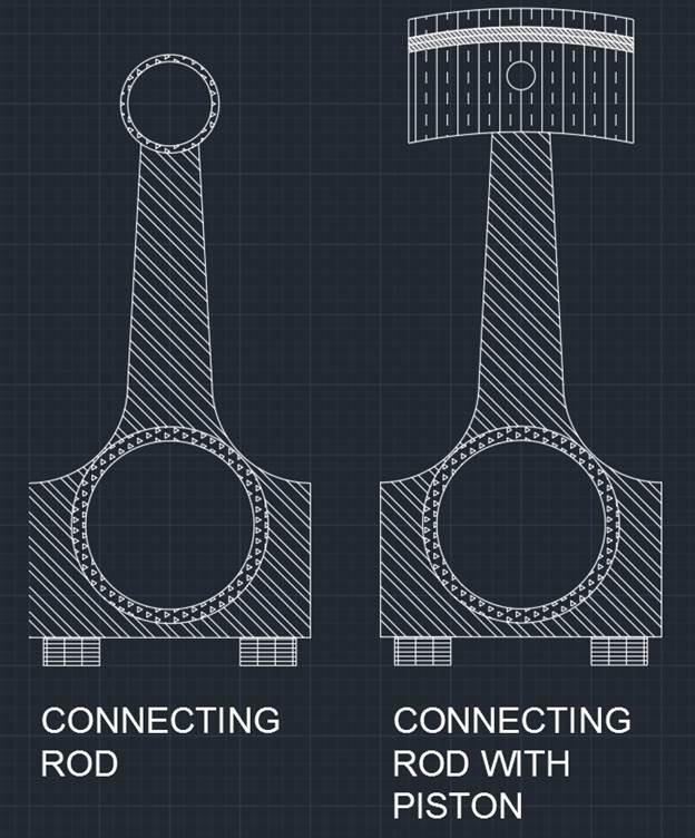
We have one last step, and the Connecting Rod (sans piston) will be complete. We still need to shade in the parts that aren’t hollow. Open up the Hatch Tool (HATCHADD). Choose any hatches you like and shade in every part except the inner 2 circles. Refer to Figure 19.
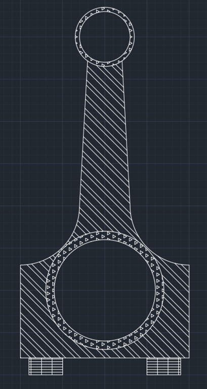
(Figure 19)
That’s how you do a Connecting Rod. All the arcs are properly centered around major gridpoints and this would be easy to even draft by hand, if needed.
PART 2: Connecting Rod (with) Piston
Now we will be going a Connecting Rod with the Piston attached. We will be working off our previous creation, so make a copy if you want to end up with both.
Select the top 2 circles, along with the hatch in between them, and then hit DEL to delete

(Figure 20)
Make a rectangle (RECTANG) following the endpoints of the one shown in Figure 21. Assuming your Object and Grid Snaps are still on, everything should work smoothly.

(Figure 21)
Select the Rectangle you’ve created and rest your mouse on the middle blue grabber of the bottom horizontal line. 3 options will pop up in a dialogue. Choose the one that says “Convert to Arc.”
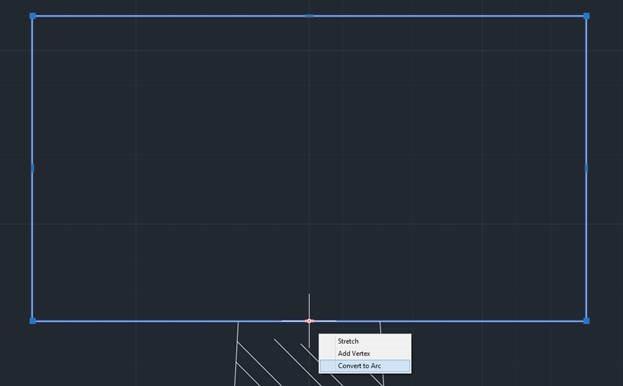
(Figure 22)
The radius of the arc doesn’t matter as much as it matters that it protrudes upward. Aim for something similar to Figure 23. It may be easier for you to turn off (F9) Grid Snap just for this part. Remember to turn it back on (F9) after. While the exact radius is not significant, it is better to make the arc as subtle as possible, and if you need to go back after and make it more evident you can. (EDIT: I actually ended up doing this later in the tutorial.)
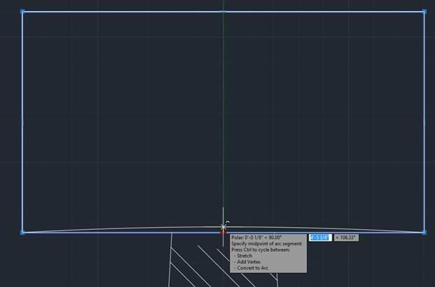
(Figure 23)
Now what we are going to do is break apart (EXPLODE) the rectangle into individual lines and then delete the top horizontal line of the rectangle.
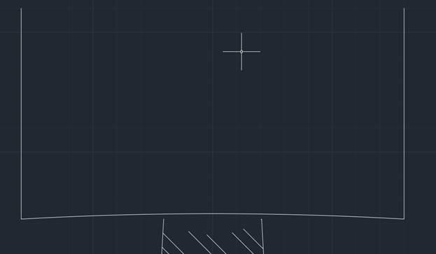
(Figure 24)
Copy the bottom arc we made onto the endpoints of the other lines. Use Figure 25 as a reference.
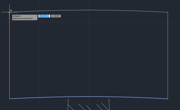
(Figure 25)
Note: I went back and made my arcs a little more arched after this.
Make a circle that has a half-inch radius and place it at the point shown in Figure 26.

(Figure 26)
Make 3 copies of the top arch and place the midpoint of each on one of the three red circles shown in Figure 27.
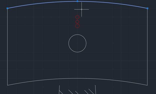
(Figure 27)
The only thing left to do is had the hatches to the Piston.
(Figure 28)
Hope you enjoyed the tutorial. See also the AutoCAD course for Architects with some free chapters.
No comments:
Post a Comment